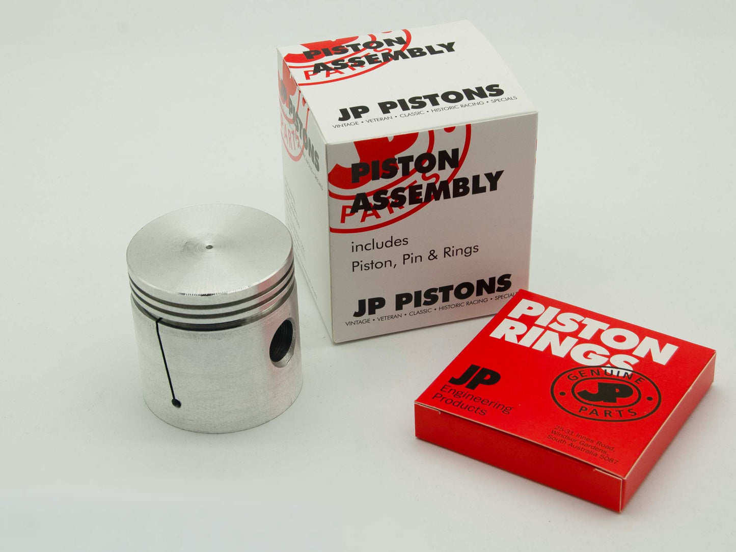
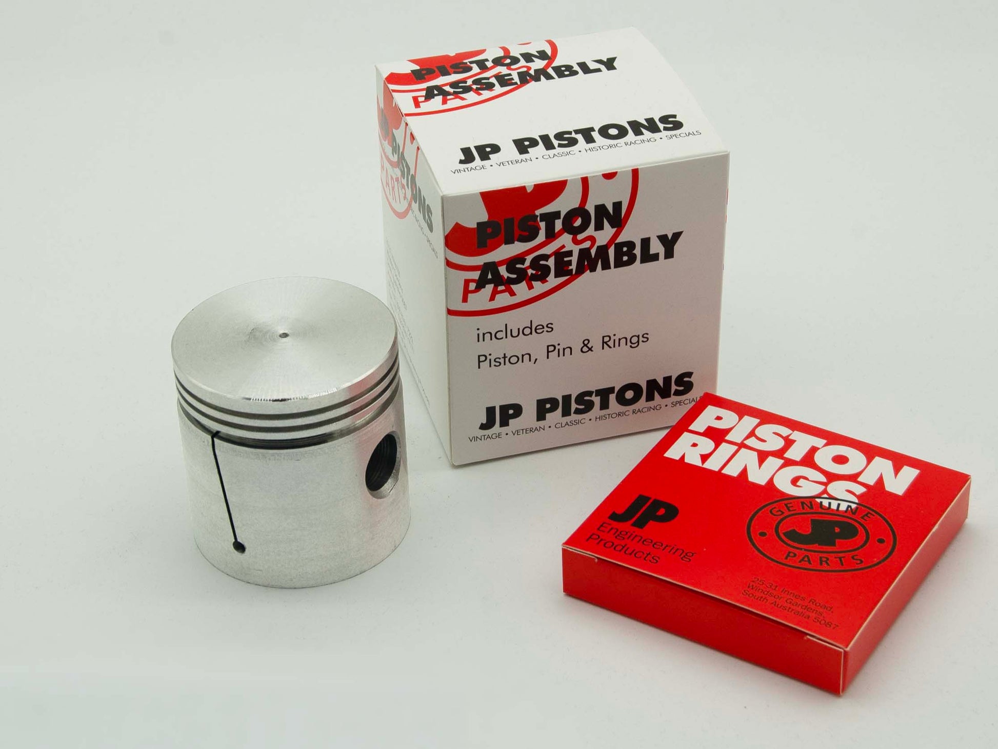
JP PISTONS
JP0127
JP0127
Alvis
14/4, TA14, TB14: 1945-51
1892cc, OHV, 4 cyl
Couldn't load pickup availability
Technical specifications
Technical specifications
Fitting instructions
Fitting instructions
PISTON FITTING INSTRUCTIONS
1. Piston assemblies must not be fitted to worn cylinder bores. The bores should be lightly honed so that the glaze is removed from the cylinder surface, and any ridge is removed from the top of the cylinder.
2. It is advisable to check the connecting rod alignment before reassembling the conrod and piston to an engine.
3. It is recommended that the piston assembly be thoroughly cleaned. Lubricate the piston assembly, paying particular attention to the piston pin. Lubricate each cylinder bore and fit each piston assembly into its cylinder by using a piston ring clamp of the appropriate size.
4. Pistons having an offset pin must be fitted with the offset towards the thrust side of the engine unless otherwise indicated.
5. All pistons which require fitting in a particular position are suitably marked on the crown.
Note: Oil consumption in a newly reconditioned motor can occur from a number of areas. The most common are: incorrect driving techniques during bedding-in, incorrectly honed bore not allowing rings to bed-in, poor gaskets or seals, oil passing down the valve guides, crankshaft or bearing wear.
This is not a complete list of all potential causes of oil consumption.
Piston to bore clearance is measured at the bottom of the skirt at right angles to the gudgeon pin.
PISTON RING FITTING INSTRUCTIONS
COMPRESSION RINGS
When fitting compression rings ensure that:
1. Any ring with an inside chamfer has the chamfer facing the top of the piston and is placed in the top ring groove.
2. Any ring with an outside chamfer or rebate has the chamfer facing the bottom of the piston and is placed in the lowest compression ring groove.
3. Chrome rings (where supplied) must be placed in the top ring groove.
4. When compression rings are marked with a dot, a “T”, or “TOP”, that face must be toward the crown of the piston.
5. Compression rings should be fitted using either a ring expander or by expanding the ring gap using the thumbs on each hand before placing the ring in the groove.
Note: Do not wind on Compression Rings.
SEGMENTAL OIL CONTROL RINGS (4 PIECE)
1. Place expander in oil ring groove.
2. Install one steel segment (rail).
3. Install spreader above steel segment.
4. Install remaining steel segment above spreader.
Do NOT fit rails under expander.
In special cases, where the piston must be passed through the cylinder bore from the bottom before rings are installed, it will be an advantage to install the spreader as the second operation. The segments should be spiralled into position, one below and one above the spreader. This overcomes the tendency for the segments becoming engaged in the oil drain slots of the expander.
When more than one oil ring is used, always fit the segmental oil ring in the upper oil groove. With any multiple piece segmental oil control system there should be no extra parts after assembly.
SEGMENTAL OIL CONTROL RINGS (3PIECE)
1. Place expander in oil ring groove.
2. Hold the expander end in place with the thumb. Wind on the lower rail.
3. Repeat instruction 2 for the top rail.
OIL GROOVE DEPTHS FOR SEGMENTAL OIL CONTROL RINGS
Ensure that when fitting new segmental oil rings to an old piston that the oil groove depths are correct. All depths are sizes below the diameter of the bore.
The correct depths for a four piece segmental oil ring are below.
Bore Size Depth
2.480”(63mm)–
2.874”(73mm) 0.290”(7.4mm)
2.875”(73.03mm)–
2.999”(76.18mm) 0.320”(8.1mm)
3.000”(76.2mm)–
.499”(88.88mm) 0.360”(9.1mm) 3.500”(88.9mm)–
4.000”(101.6mm) 0.400”(10.2mm)
Chrome plated rings MUST NOT be fitted to chrome plated cylinder bores.
Always use new circlips. JP PISTONS are not weight matched to O.E. specifications
SEEGER CIRCLIPS
When fitting Seeger circlips ensure the radiused surface is against the gudgeon pin.


